


In many industrial processes, a dust extraction system does more than clean the air. It must capture, convey, separate and route extracted material to a collection, storage, recovery or reuse point. In woodworking, furniture manufacturing, plastics processing, food production, textiles, composites and certain metalworking applications, material removed from the work area does not simply disappear. It must be managed as part of the technical process.
This is where pneumatic conveying becomes part of an extraction system. Air carries particles, sawdust, wood chips, dust, fibers, granules and other lightweight materials through ductwork to separation and collection equipment. In a correctly designed system, extracted material reaches filters, cyclones, silos, hoppers, containers, collection bags or recovery lines in a controlled manner. Poor design causes deposits in the ductwork, blockages, reduced airflow, high energy consumption, dust in the production area and unplanned downtime.
Pneumatic conveying should not be confused with suction alone. Extraction captures contaminated air. Pneumatic conveying moves solid material in an airflow along a route designed for the required velocity and pressure. In an industrial dust extraction system, these functions overlap: the system captures contaminated air while carrying particles to the separation point.
Pneumatic conveying is essential for companies that generate significant amounts of extracted material, such as furniture factories and woodworking facilities. Sawdust, sanding dust and chips must be collected efficiently to keep the workplace clean, protect machinery and enable the controlled recovery or reuse of wood residues where appropriate. In other industries, pneumatic conveying removes powders, fibers and particles generated by production processes.
A well-engineered system involves more than ductwork and a fan. It requires effective source capture, suitable transport velocity, routes without dead zones, efficient separation, controlled discharge, appropriate storage equipment and planned maintenance.
What pneumatic conveying means in industrial dust extraction
Pneumatic conveying is the movement of solid material through pipework by an airflow. In dust extraction systems, it is normally achieved by suction: negative pressure draws contaminated air and particulate material away from the work area.
The extracted material can vary considerably. Woodworking produces sawdust, chips, sanding dust and machining residues. Food manufacturing can generate powders, husks, organic particles and process residues. Textile processes release fibers and lightweight particles. Plastics processing can produce fine granules, dust and particles from cutting or milling. Pneumatic conveying can also handle fine metallic dust, but abrasion, sparks and the material characteristics require additional attention.
Within an extraction system, material is captured at source, entrained in the airflow, conveyed through ductwork and separated in dedicated equipment. Separation may take place in a cyclone, filter, mechanical separator or combined system. After separation, the material is discharged into bags, containers, silos or hoppers.
An effective pneumatic conveying system must keep the material moving until it reaches its destination. If air velocity falls too far, particles settle inside the ductwork. Excessive velocity increases energy consumption, noise and wear. Design must therefore balance capture, transport, separation and energy use.
The difference between dust extraction and pneumatic conveying
The main purpose of industrial dust extraction is to capture contaminated air. Pneumatic conveying is intended to move solid material in an airflow. The two functions work together in many applications, but they are not identical.
A welding-fume extraction system, for example, can capture smoke and fine particles without having to convey a large mass of material. A woodworking extraction system, by contrast, must continuously transport sawdust, dust and chips. Pneumatic conveying is therefore a central part of the system.
This distinction matters because the sizing criteria differ. Removing contaminated air focuses on airflow, capture and filtration. Pneumatic conveying also requires consideration of material pickup and transport velocity, settlement risk, abrasion, route length, bends, branches, discharge and storage.
A system can extract air while conveying material poorly. This occurs when ducts are oversized, air velocity is too low, routes are too long or branches are unbalanced. Material then accumulates in the ductwork, gradually causing airflow loss, blockages and operating risks.
Industrial extraction projects must account for this distinction from the outset. Where a significant quantity of material is captured, the installation must be designed as a dust extraction system with pneumatic conveying, not merely as a ventilation network.
Where pneumatic conveying is used in dust extraction systems
Pneumatic conveying is used across many industries, but it is especially important where processes generate lightweight solids, particles or powders that need to be collected quickly.
Woodworking is an obvious application. Circular saws, planers, milling machines, CNC equipment, calibrating sanders and sanding stations all produce material that must be captured and conveyed. Sawdust and dust should not remain around machinery because they affect housekeeping, safety, machining accuracy and equipment service life.
In furniture factories, pneumatic conveying collects material from several machines connected to a centralized extraction network. The material can be routed to filters, silos, hoppers or other collection systems.
Powders and particles in food production must be managed carefully to reduce contamination and deposits. Depending on the material, the system must also support the required hygiene and cleaning procedures.
In plastics processing, pneumatic conveying can remove particles produced during machining, milling, cutting and handling. Electrostatic charging may also need to be considered for certain materials.
Textile and composite fibers present specific challenges. They can agglomerate, load filters differently from mineral dust and require capture and filtration designed for fibrous material.
Applications of pneumatic conveying in dust extraction
| Industry / application | Extracted material | Important components | Technical challenges | Recommended approach |
|---|---|---|---|---|
| Woodworking | Sawdust, wood chips, sanding dust | Machine connections, ductwork, fan, filter, silo | Deposits, sparks, high material volume | Centralized extraction with pneumatic conveying and controlled collection |
| Furniture manufacturing | Fine dust, machining residues, wood particles | Downdraft benches, filters, rotary airlocks, hoppers | Simultaneous machine operation, rapid filter loading | Balanced network, correctly sized filtration and automatic discharge |
| Plastics processing | Fine particles, dust, lightweight granules | Local capture, ductwork, cartridge filters | Static electricity, lightweight particles | Point capture and filtration matched to the material |
| Food production | Organic powders, husks, fine particles | Hoods, filters, separators, hoppers | Hygiene, cleaning, accumulation | Easy-to-clean systems with separate collection |
| Textiles | Fibers, lint, lightweight particles | Backdraft extraction walls, filters designed for fibers | Clogging, agglomeration, lightweight material | Wide capture area and filtration designed for fibrous material |
| Light metalworking | Metallic dust, abrasive particles | Hoods, wear-resistant ductwork, robust filters | Abrasion, sparks, particle weight | Application-specific design with suitable protection measures |
| Sanding lines | Fine dust and abrasive material | Downdraft benches, ductwork, filters | Rapid dispersion, filter loading | Capture close to source and sufficient filter area |
| Wood-residue recovery | Collected sawdust and chips | Silos, hoppers, rotary airlocks, conveyors | Discharge, storage, process continuity | Integrated collection and routing to a controlled recovery stream |
Main components of a pneumatic conveying system
A dust extraction system with pneumatic conveying contains several components that must be sized together. It is not enough for each item to perform well in isolation; the installation must operate as one system.
The first component is source capture. Machine connections, hoods, downdraft benches, backdraft extraction walls and extraction inlets can all be used. Capture should be positioned as close as possible to the point where material is generated.
The second component is the duct network, which carries both air and extracted material. Diameter, routing, the number of bends and airtightness directly influence pneumatic conveying performance.
The third component is the fan. It generates the pressure difference required to move the air and material. Fan selection must account for airflow, pressure and the characteristics of the conveyed material.
The fourth component is separation. Solid material must be removed from the air stream using cyclones, bag filters, cartridge filters or combined systems, depending on the application.
The fifth component is discharge. Collected material must leave the filter or separator without obstructing the system. Rotary airlocks, collection bags, containers, hoppers, silos and mechanical conveyors are used for this purpose.
The sixth component is automation. Automatic dampers, sensors, filter monitoring and fan control can improve energy efficiency and support predictive maintenance.
Capturing extracted material at source
Every pneumatic conveying system begins with effective capture. If material is not collected properly at the machine, the rest of the installation cannot fully compensate. Source capture reduces dispersion, lowers dust levels in the facility and makes conveying more efficient.
Many woodworking machines have dedicated extraction connections, but attaching a hose or duct does not guarantee good performance. The connection must have the correct diameter and sufficient airflow must be available. Arbitrary diameter reductions or too many machines connected to one branch will reduce extraction.
During sanding, capture should be as close as possible to the contact area. Fine sanding dust disperses rapidly and can reach the operator’s breathing zone. Downdraft benches, extraction tables and backdraft walls can be more effective than a distant extraction inlet.
On machines that produce chips or sawdust, capture should follow the natural discharge direction of the cutting tool. If the extraction point is placed against that direction, some material will disperse before it can be collected.
Good capture reduces the load on the whole system. The more consistently material enters the airflow at source, the more stable the duct network and filtration will operate.
Ductwork for pneumatic conveying
Ductwork is one of the most important parts of a dust extraction system with pneumatic conveying. It must carry air and material without blockages, deposits or excessive pressure loss.
Duct diameter must be selected correctly. If it is too small, velocity may be high but pressure losses increase and the fan must work harder. If it is too large, air velocity falls and material can settle. Transport velocity is critical because the material must remain entrained until it reaches the separator.
Routing also requires careful design. Abrupt bends encourage deposits and increase wear. Poorly designed branches create airflow imbalances between capture points. Long runs increase pressure loss and may require a higher-pressure fan. Leaking joints reduce the airflow available at the machinery.
Ductwork carrying abrasive material must resist wear. Particles moving at speed strike the duct walls, particularly at bends. Material, thickness and fitting geometry must be selected accordingly.
For combustible materials or processes that can generate sparks, the duct network must form part of the safety concept. Conveying the material is not enough; deposits, ignition sources and conditions that increase incident risk must be addressed.
The fan in pneumatic conveying
The fan moves air through the system. Centrifugal fans are commonly used in industrial dust extraction because they can provide the airflow and pressure required by a duct network.
A fan is not selected by motor power alone. Selection is based on required airflow and total system pressure, including losses through capture points, ductwork, bends, filters, separators, valves and the discharge path.
In pneumatic conveying, the fan must maintain the velocity needed to move the material. If airflow drops, particles can settle. An oversized fan increases energy consumption, noise and wear.
Fan position relative to filtration and the conveyed material is another important consideration. In some arrangements, the fan handles cleaner air downstream of separation. In others, it may be exposed to particles. The correct configuration depends on the system, contaminant and required level of protection.
The fan must be treated as part of the complete installation. A high-performance fan cannot compensate for poorly sized ductwork or ineffective capture.
Separating extracted material from the air
After travelling through the ductwork, extracted material must be separated from the air stream. Ineffective separation can allow particles to reach the discharge air, overload final filters or contaminate the working environment.
Cyclones are commonly used to remove heavier particles. They use the rotational movement of the air to separate solids and are useful where large amounts of material such as sawdust or wood chips are handled.
Bag filters retain dust and fine particles. In woodworking systems, they can operate in combination with cyclones or other collection equipment. Cartridge filters suit fine particles and compact applications, but must be selected for the specific material.
Many installations use staged separation: larger particles are removed first, followed by finer dust. This approach protects the filters and improves system stability.
Separation must be coordinated with discharge. If material is separated but not removed correctly from the equipment, the system can block or lose efficiency.
Rotary airlocks and controlled discharge
Rotary airlock valves are important in pneumatic conveying extraction systems. They discharge collected material from filters, cyclones, hoppers or silos while maintaining separation between zones at different pressures.
Without controlled discharge, material can accumulate inside the separator or filter. This increases resistance, reduces airflow and can stop production. A rotary airlock provides continuous material discharge and supports uninterrupted operation.
In woodworking, rotary airlocks handle sawdust, dust and fine chips. Other industries use them for powders, granules and solid particles. Selection depends on material throughput, particle size, density, moisture and whether the material is abrasive or sticky.
An unsuitable rotary airlock can cause blockages, air leakage and premature wear. It should be selected for the application, not only by connection size.
Silos and hoppers for collected material
Simple bags and containers are insufficient where large quantities of material are collected. Silos and hoppers provide controlled storage and separate the extracted material flow from the production process.
In woodworking facilities, sawdust and chips can be routed to metal silos. Depending on their composition and the factory requirements, the material can later be discharged, transported or transferred to an authorized recovery stream. Organized storage is much more efficient than manual handling in facilities that generate large volumes of wood residues.
Hoppers can provide temporary accumulation, mixing or feeding to downstream equipment. Depending on the material, they may include extraction systems, conveyors, screw conveyors or other mechanical equipment.
Storage capacity must match the material generation rate. An undersized silo fills quickly and interrupts production; an oversized silo may be costly and difficult to integrate. Discharge must also prevent compaction, bridging and blockage.
Routing material for recovery or reuse
Extracted material is not always a waste stream without value. In some industries, it can be recovered or reused. In woodworking, sawdust and chips can be routed to storage, recycling or other authorized processes, depending on the material and company requirements.
Recovery requires clean, organized collection. Material mixed with metal, plastic, paint or other contaminants may be more difficult to reuse. Separate collection routes can therefore be used for different materials.
Material can be routed using ductwork, valves, dampers, hoppers, screw conveyors, conveyors and auxiliary mechanical systems. In a well-organized factory, the extraction system does not stop at the filter; it forms part of a complete material-management flow.
This approach is especially useful in facilities that generate large volumes of residues. Instead of being handled manually, material is collected automatically and directed to a defined destination.
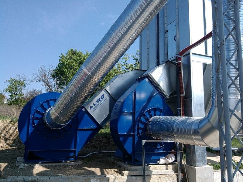
Common pneumatic conveying problems
Material deposits in ductwork are one of the most frequent problems. They occur when air velocity is too low, routes are poorly designed or branches are unbalanced. Deposits reduce the free duct area and can eventually cause blockages.
Filter loading is another common issue. Very fine, damp, sticky or high-volume material can load filters rapidly. Increasing filter area, adding a pre-separation stage or selecting a more suitable filter medium may be required.
Airflow loss often results from leaking joints, damaged ductwork or incorrectly adjusted dampers. Air drawn through cracks reduces the flow available at the machinery.
High noise levels can indicate excessive velocity, an oversized fan, vibration or poor routing. Accelerated wear at bends can result from abrasive material or excessive transport velocity.
Discharge blockages occur when material does not flow correctly, the rotary airlock is unsuitable or the hopper geometry does not match the material behavior.
Common mistakes in pneumatic conveying design
The first mistake is selecting ductwork without calculation. Diameters must be based on the required airflow and material characteristics, not availability or visual estimation.
The second is connecting too many machines to one network without assessing simultaneous operation. If several machines run at the same time, available airflow may be insufficient.
The third is excessive use of flexible ducting. Flexible hose is useful for short machine connections, but long sections create pressure loss and can accumulate material.
The fourth is overlooking the discharge of collected material. Separation without controlled removal leads to accumulation and blockage.
The fifth is selecting a fan by motor power alone. Fan selection must be based on airflow, pressure and the actual system configuration.
The sixth is mixing incompatible materials. Some collected materials must remain separate for safety, filtration or recovery purposes.
The seventh is failing to provide maintenance access. Ductwork, filters, rotary airlocks and hoppers that are difficult to inspect will receive less maintenance and lose efficiency.
Maintenance of pneumatic conveying systems
Maintenance is essential for any dust extraction system with pneumatic conveying. Air, particles, filters, valves and mechanical components are all subject to loading, wear and gradual imbalance.
Ductwork should be inspected for deposits, cracks, leaking joints and wear. Bends are critical areas, especially with abrasive material. Flexible connections should be checked for cracks, crushing and sharp bends that reduce airflow.
Filters should be monitored through differential pressure, visual inspection and planned replacement. If filters remain in service for too long, airflow falls and material transport becomes unstable.
Rotary airlocks should be inspected for blockages, wear, leakage and consistent operation. Silos and hoppers require checks for accumulation, material bridging, uneven discharge and problems with their reclaim systems.
A good maintenance program reduces unplanned stoppages. In pneumatic conveying, a small issue can quickly affect the complete material flow.
Automation in pneumatic conveying
Automation can significantly improve a dust extraction system with pneumatic conveying. Not every installation requires complex controls, but intelligent operation can reduce energy consumption and improve stability in factories with several machines and variable production flows.
Automatic dampers can open extraction only at active machines, avoiding energy use at idle points. Variable frequency drives can adapt fan speed to actual airflow demand. Sensors can monitor filter differential pressure, silo level and rotary-airlock operation.
Warning systems can identify loaded filters, blockages, high hopper level and declining performance before production is affected.
Automation does not replace correct design. An incorrectly sized system does not become effective simply because it is automated. In a properly designed installation, however, automation improves efficiency and predictability.
Safety in pneumatic conveying installations
Pneumatic conveying can involve risks when material is combustible, abrasive or hot, or when sparks can enter the system. Wood dust and sawdust require careful management. Hot particles or sparks may enter metalworking ductwork. Certain organic powders in food production can also require specific measures.
Safety begins by preventing accumulation. Deposits reduce performance and can create additional hazards. Where process assessment shows they are necessary, the system should include appropriate components such as spark detection and extinguishing, explosion relief panels, isolation dampers, separators or other protective measures.
Collected material must be stored correctly. Silos and hoppers should be designed for the material volume and flow behavior, with safe and controlled discharge.
Operators and maintenance personnel must be trained. Safe extraction depends on correct operation as well as suitable equipment.
How to design pneumatic conveying within a dust extraction system
Correct design begins with the material. Its particle size, density, abrasiveness, moisture, combustibility and generation rate must be established.
The sources are then assessed: the number of machines, simultaneous operation, airflow required at each point, connection sizes and positions. The designer determines whether the system should be local, centralized or hybrid.
Ductwork design follows. Diameters, routes, bends, branches and dampers are selected to maintain transport velocity while controlling pressure losses.
Separation and filtration equipment is then specified. Coarse material may require cyclones or mechanical separators, while fine particles require suitable filters. Large material volumes call for silos, hoppers and controlled discharge.
The fan is selected last, after total airflow and system pressure have been calculated. Maintenance access, safety, noise, automation and future expansion are then reviewed.
Frequently asked questions about pneumatic conveying in dust extraction systems
1. What is pneumatic conveying in industrial dust extraction?
Pneumatic conveying moves extracted material through ductwork in an airflow. It allows sawdust, dust, fibers, powders and particles to be collected and routed to filters, cyclones, silos or hoppers.
2. What is the difference between dust extraction and pneumatic conveying?
Dust extraction captures contaminated air, while pneumatic conveying moves the captured solid material through ductwork. The two functions work together in many industrial systems.
3. Where is pneumatic conveying most commonly used?
It is widely used in woodworking, furniture manufacturing, food production, textiles, plastics, composites and other industries that generate dust, particles or lightweight material.
4. Why is air velocity important in the ductwork?
Velocity must be high enough to keep material moving. Low velocity causes deposits and blockages; excessive velocity increases energy consumption, noise and wear.
5. What is the role of ductwork in pneumatic conveying?
Ductwork carries the air and extracted material to the separation point. Diameter, routing, airtightness and the number of bends directly affect performance.
6. What happens when ductwork is sized incorrectly?
Incorrect sizing can cause deposits, pressure loss, weak source capture, blockages, high energy consumption and reduced machine performance.
7. What is the fan’s role in a pneumatic conveying system?
The fan creates the pressure difference required to move air and material. It must be selected for the airflow, pressure and configuration of the complete system.
8. What do cyclones and filters do?
Cyclones separate heavier particles from the airflow, while filters retain fine particles. They are often used together for effective staged separation.
9. What is a rotary airlock?
A rotary airlock discharges collected material from filters, cyclones, hoppers or silos while maintaining separation between zones at different pressures.
10. When is a silo required?
A silo is used when large quantities of material such as sawdust or wood chips are collected. It provides organized storage and controlled discharge.
11. Can extracted material be recovered or reused?
Yes, in certain industries. Cleanly collected sawdust and wood chips, for example, can be routed to storage, recycling or other authorized processes.
12. What are the most common pneumatic conveying problems?
Common problems include deposits in ductwork, loaded filters, airflow loss, discharge blockages, noise, bend wear and excessive energy consumption.
13. How can duct blockages be prevented?
Correct duct sizing, sufficient transport velocity, well-designed routes, suitable bends, balanced branches and regular maintenance help prevent blockages.
14. Is automation necessary in a pneumatic conveying system?
Not in every installation, but it can be valuable. Automation can control dampers, airflow, filter pressure, silo levels and material-discharge equipment.
15. How is a pneumatic conveying system designed correctly?
Design starts with the conveyed material, contamination sources, machine count, simultaneous operation, routes, airflow, pressure, filtration, separation, discharge and storage. The fan is selected only after the complete system has been calculated.
Pneumatic conveying is essential wherever extracted material must be collected and routed in a controlled manner. In woodworking, furniture production, food manufacturing, textiles, plastics and other industrial applications, the system must do more than capture contaminated air: it must carry material to filtration, separation, storage or recovery.
An effective installation requires correct source capture, properly sized ductwork, suitable transport velocity, an appropriately selected fan, efficient separation, controlled discharge and planned maintenance. Silos, hoppers, rotary airlocks, filters and automation are not secondary accessories; they are important parts of the technical process.
Design errors can cause deposits, blockages, loaded filters, high energy consumption and unplanned downtime. Pneumatic conveying must therefore be calculated and integrated into the industrial dust extraction project from the beginning.
In a well-organized factory, extracted material is not allowed to collect around machinery or in the corners of the facility. It becomes a controlled flow that is captured, separated and routed to a defined destination. This is the difference between basic air extraction and a complete industrial system designed for efficiency, safety and production continuity.


